
 I saw a brief case study from a foundation contractor who had installed a proprietary pile system for a building in Northwest Washington, DC. Being somewhat familiar with the subsurface conditions and typical building heights in the area, I immediately doubted whether a deep foundation system was necessary. You will have to forgive my skepticism about this sort of thing; I have seen it a lot, and it seems to be getting more prevalent.
You see, when you get away from the filled-in marshlands, the soil conditions in the DC metro area are not that bad. Generally, new buildings are low to mid-rise (at least to this former New Yorker). Yet deep foundations or ground improvement are selected as the foundation systems for many projects. This seems to be the result of low-cost, commoditized geotechnical services, which typically do not include site-specific engineering due to budget limitations.
Arguing that low-cost geotechnical services lead to higher construction costs is straight-forward, but a little abstract for those unfamiliar with foundation engineering practice. Nothing beats an example with real subsurface data to illustrate the process. Therefore, I found a geotechnical report online for a public building project in upper Northwest Washington, DC and performed my own analysis of the bearing capacity. This particular report displays a mixture of good and poor practice. It is probably neither the cheapest nor the most expensive approach to exploring the site.
The site is well above sea level and slopes slightly. The lowest level of the building will be near grade at one end of the site and fully below grade at the other. The subsurface conditions are somewhat variable, with fill, sand, silt and clay soils reported. Groundwater is deep and is unlikely to be encountered during construction. One good practice shown in the report is that the hammer type used in obtaining Standard Penetration Test (SPT) samples is reported on the boring logs. Different hammer types deliver different amounts of energy and this significantly affects the blowcounts recorded. Failing to record the hammer type can result in serious errors in interpreting the data. Since a safety hammer was used, the blowcounts recorded are compatible with many SPT correlations without modification.
I have reproduced one of the geologic sections below (geologic sections are often not included in geotechnical reports, but are useful to the foundation designer and contractor for understanding the subsurface conditions). The sample locations, SPT blowcounts and Unified Soil Classification System (UCSC) symbols are shown. The horizontal scale is highly exaggerated and Boring No. 2 is projected farther to the section than one might like, resulting in a distorted stratum break. I have changed extraneous details (boring numbers, elevations) to obscure the identity of the site. Most of the soil samples included clayey sand (SC) underlain by low plasticity and high plasticity silt (ML and MH, respectively).
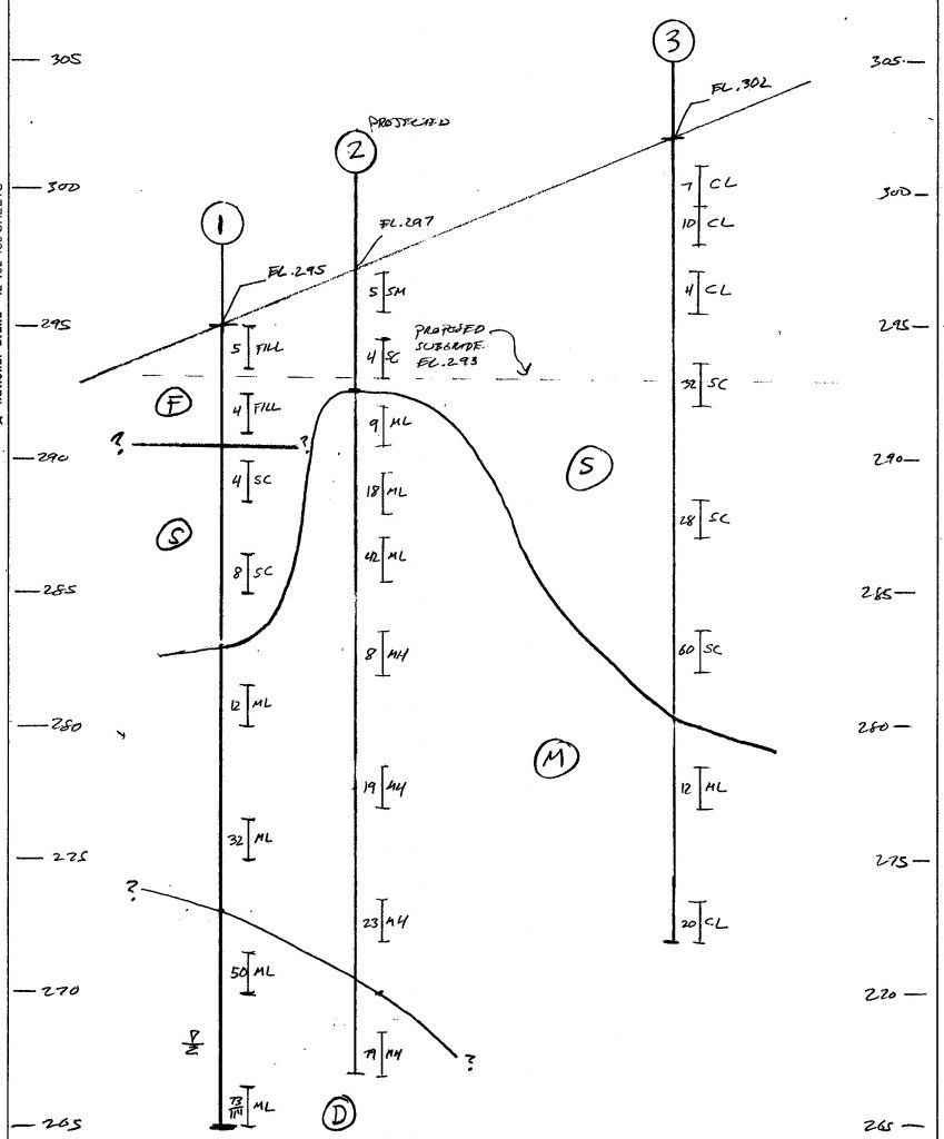
The stratification is my own interpretation of the subsurface data. The geotechnical engineer took a common, yet overly simplistic approach in which soil strata are identified by UCSC symbol alone. However, the soil does not care about our classification systems and will behave according to the geologic process that produces each stratum. Based on sample descriptions on the boring logs, geologic maps and generalized strata descriptions used by WMATA (Adjacent Construction Projects Manual, 5th Ed.), I determined that the sand layer appears to be a Pliocene gravelly sand and clay deposit. I have seen other references identify this type of material as part of the “Terrace” or “upland” Coast Plain deposits. The silt was more difficult to classify because the mapping and the sample descriptions are not well-matched, but it is likely from the Upper Cretaceous period. Some of the silt samples include mica and appear consistent with decomposed rock, which is also common in the area. I delineated between silt and decomposed rock based on the significant increase in blowcounts in the mica-containing silt. Note that the boring logs grouped multiple samples into one description. This is poor practice because it makes identifying strata changes more difficult.
It is important to try to place subsurface data into a geologic context because it allows a better understanding of engineering properties and behavior of the soil. When borings are made, the statistical sample size recovered and subjected to SPTs is very small. The sample size subjected to laboratory testing is even smaller and probably not statistically representative. Identifying the geologic origin of soil samples allows a priori information to be used to reduce the uncertainty associated with the data. I was able to group the shallow clay (CL) samples in Boring No. 3 with the clayey sand samples based on geologic references suggesting that these were samples of the same deposit with varying gradations. Removing the suspected decomposed rock samples from the silt layer reduced the variability in the blowcounts in that stratum. Since this process reduces uncertainty, less arbitrary conservatism is necessary to manage design risk.
With the samples grouped into strata, I averaged the blowcounts for each stratum to use in estimating engineering properties. The average blowcount for the gravelly sand and clay stratum is about 16 and the average blowcount for the silt stratum is about 20. If the suspected decomposed rock samples had been classified as silt, the average blowcounts would be over 30. The strength of these two strata are similar and an internal friction angle of about 32 degrees can be used for both.
There seems to be an infinite number of ways to estimate the bearing capacity of soil. The District of Columbia Building Code includes presumptive values for sand and silt of 2,000 psf and 1,500 psf, respectively, which can be used with no substantiation. Low-cost firms will often report these presumptive values because it requires almost no work. However, these are not presumptive values for local soils. They are taken from the International Building code and have to be reliable for a huge variety of conditions and therefore, must be nearly lower bound values. The presumptive bearing capacity values do not even account for the density of the soil. We can do better.
The traditional approach to bearing capacity is the theoretical bearing capacity equation developed by Terzaghi and modified by others. This equation, however, requires that the width and depth of the footing be known. I assumed a three-foot minimum footing width, a footing depth of two feet below the basement subgrade and a soil unit weight of 120 pcf. Using the Vesic bearing capacity factors and a traditional factor of safety of three, I estimated an allowable bearing capacity of about 3,700 psf (See Bowles. Foundation Analysis and Design). This value is probably still conservative. The bearing capacity equation makes a crude estimate of ultimate strength. The traditional factor of safety is intended to simultaneously provide reliability and some displacement control under service load. However, since the equation does not estimate settlement there is an element of arbitrary conservatism in the factor of safety.
Bowles provides a correlation of allowable bearing capacity with SPT blowcounts that is based on limiting settlement to one inch. It is typically understood, or at least assumed, that presumptive bearing capacity and other methods will limit elastic settlement to about the same magnitude. Typically for footing design problems, settlement controls over strength. Using the same assumed footing geometry as I used for the bearing capacity equation, this method provided an allowable bearing capacity of 7,800 psf.
The presumptive building code value and Bowles method vary by a factor of about four. So what is the actual bearing capacity? There is no simple answer. Part of the problem is the iterative nature of design, which is often not captured in bearing capacity estimates. The bearing capacity is a function of footing size and depth and the footings cannot be configured without estimating the bearing capacity. It is also important to understand that the bearing capacity is not a material property, but a prediction of the behavior of the ground, the foundation and the loading delivered by the structure as a system. This system is subject to uncertainty in the mathematical models used to predict its performance, the interactions of the mathematical models and initial conditions in those models.
For this project, the geotechnical engineer recommended a bearing capacity of 3,000 psf. My sense is that a slightly higher value is correct, but it might require a few design iterations or a more detailed review of the data to demonstrate it. However, a bearing capacity that is double the presumptive code value appears justified, if not a little conservative. For a single-family home or one-story commercial building, doubling or even quadrupling the bearing capacity probably does not produce construction cost-savings. However, for a more significant structure, a significant increase in bearing capacity can eliminate unnecessary deep foundations or ground improvement, reducing construction cost, schedule and risk. For significant projects, these cost savings offset the additional costs for more comprehensive subsurface exploration and foundation engineering services at an attractive rate of return. Therefore, comprehensive, site-specific geotechnical and foundation engineering services should be standard practice on these projects.
The information and statements in this document are for information purposes only and do not comprise the professional advice of the author or create a professional relationship between reader and author.